使用OpenGL实现OpenCV的remap功能

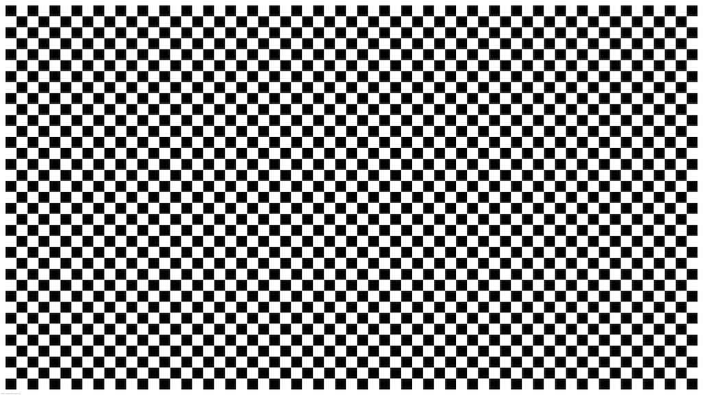
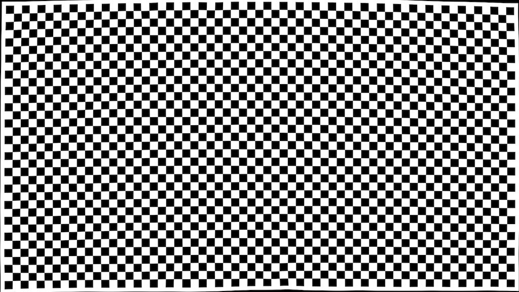
我们希望对输入图片根据Distort程序进行畸变处理:

1
2
3
4
5
6
7
8
9
10
11
12
13
14
15
16
17
18
19
20
21
22
23
24
25
void Distort(const float &x_src,
const float &y_src,
const cv::Mat &control_points,
const float &r2,
const cv::Mat &W,
float &x_dst,
float &y_dst) {

int pts_num = control_points.rows;

x_dst = 0;
y_dst = 0;
for (int i = 0; i < pts_num; i++) {
float x_diff = x_src - control_points.at<cv::Vec2f>(i)[0];
float y_diff = y_src - control_points.at<cv::Vec2f>(i)[1];

float kernel = 1.f / sqrt(x_diff * x_diff + y_diff * y_diff + r2);

x_dst += kernel * W.at<float>(i, 0);
y_dst += kernel * W.at<float>(i, 1);
}

x_dst += (W.at<float>(pts_num, 0) + W.at<float>(pts_num + 1, 0) * x_src + W.at<float>(pts_num + 2, 0) * y_src);
y_dst += (W.at<float>(pts_num, 1) + W.at<float>(pts_num + 1, 1) * x_src + W.at<float>(pts_num + 2, 1) * y_src);
}
输入图像 处理后图像
chessboard_input chessboard_warp

可以根据Distort程序,生成OpenCV中cv::remap函数所需的map1map2映射矩阵,然后再使用cv::remap对输入图片进行处理。为了加速这个图像处理速度,尝试使用OpenGL,通过显卡实现类似于cv::remap函数的功能:

1
2
3
4
5
6
7
8
9
10
11
12
13
14
15
16
17
18
19
20
21
22
23
24
25
26
27
28
29
30
31
32
33
34
35
36
37
38
39
40
41
42
43
44
45
46
47
48
49
50
51
52
53
54
55
56
57
58
59
60
61
62
63
64
65
66
67
68
69
70
71
72
73
74
75
76
77
78
79
80
81
82
83
84
85
86
87
88
89
90
91
92
93
94
95
96
97
98
99
100
101
102
103
104
105
106
107
108
109
110
111
112
113
114
115
116
117
118
119
120
121
122
123
124
125
126
127
128
129
130
131
132
133
134
135
136
137
138
139
140
141
142
143
144
145
146
147
148
149
150
151
152
153
154
155
156
157
158
159
160
161
162
163
164
165
166
167
168
169
170
171
172
173
174
175
176
177
178
179
180
181
182
183
184
185
186
187
188
189
190
191
192
193
194
195
196
197
198
199
200
201
202
203
204
205
206
207
208
209
210
211
212
213
214
215
216
217
218
219
220
221
222
223
224
225
226
227
228
229
230
231
232
233
234
235
236
237
238
239
240
241
242
243
244
245
246
247
248
249
250
251
252
253
254
255
256
257
258
259
260
261
262
263
264
265
266
267
268
269
270
271
272
273
274
275
276
277
278
279
280
281
282
283
284
285
286
287
288
289
290
291
292
293
294
295
296
297
298
299
300
301
302
303
304
305
306
307
308
309
310
311
312
313
314
315
316
317
318
319
320
321
322
323
324
325
326
327
328
329
330
331
332
333
334
335
336
337
338
339
340
341
342
343
344
345
346
347
348
349
350
351
352
353
354
355
356
357
358
359
360
361
362
363
364
365
366
367
368
369
370
371
372
373
374
375
376
377
378
379
380
381
382
383
384
385
386
387
388
389
390
391
392
393
394
395
396
397
398
399
400
401
402
403
404
405
406
407
408
409
410
411
412
413
414
415
416
417
418
419
420
421
422
423
424
425
426
427
428
429
430
431
432
433
434
435
436
437
438
439
440
441
442
443
444
445
446
447
448
449
450
451
452
453
454
455
456
457
458
459
460
461
462
463
464
465
466
467
468
469
470
471
472
473
474
475
476
477
478
479
480
481
482
483
484
485
486
487
488
489
490
491
492
493
494
495
496
497
498
499
500
501
502
503
504
505
506
507
508
509
510
511
512
513
514
515
516
517
518
519
520
521
522
523
524
525
526
527
528
529
530
531
532
533
534
535
536
537
538
539
540
541
542
543
544
545
546
547
548
549
550
551
552
553
554
555
556
557
558
559
560
561
562
563
564
565
566
567
568
569
570
571
572
573
574
575
576
577
578
579
580
581
/*
* @Author: Hanjie Luo luohanjie@gmail.com
* @Date: 2023-01-11 16:55:10
* @LastEditors: Hanjie Luo luohanjie@gmail.com
* @LastEditTime: 2023-01-29 19:24:09
* @FilePath: /my_slam/tests/OpenGL/test_distorted_image.cpp
* @Description:
*
* Copyright (c) 2023 by CVTE, All Rights Reserved.
*/

#include <stdio.h>
#include <stdlib.h>
#include <iostream>
#include <thread>

// Include GLEW
#include <GL/glew.h>

// Include GLFW
#include <GLFW/glfw3.h>

#include <opencv2/opencv.hpp>

// shader
// -------------------------------------------------------------------------------------------
// The vertex shader is a program on the graphics card that processes each vertex and its attributes as they appear in the vertex array.
// Its duty is to output the final vertex position in device coordinates(Device X and Y coordinates are mapped to the screen between -1 and 1. y axis is positive above the center. x axis is positive in the right the center.) and to output any data the fragment shader requires.
// That's why the 3D transformation should take place here. The fragment shader depends on attributes like the color and texture coordinates, which will usually be passed from input to output without any calculations.

// Apart from the regular C types, GLSL has built-in vector and matrix types identified by vec* and mat* identifiers. The type of the values within these constructs is always a float.
// The number after vec specifies the number of components (x, y, z, w) and the number after mat specifies the number of rows /columns. Since the position attribute consists of only an X and Y coordinate, vec2 is perfect.
// The final position of the vertex is assigned to the special gl_Position variable, because the position is needed for primitive assembly and many other built-in processes. For these to function correctly, the last value w needs to have a value of 1.0f.

// Each shader can specify inputs and outputs using in and out keywords and wherever an output variable matches with an input variable of the next shader stage they're passed along. The vertex and fragment shader differ a bit though.
// The vertex shader receives its input straight from the vertex data.

const char* vertex_shader_source =
"#version 330 core\n"
"layout(location=0) in vec2 Position;\n"
"void main()\n"
"{\n"
" gl_Position = vec4(Position, 0.0, 1.0);\n"
"}\0";

// The output from the vertex shader is interpolated over all the pixels on the screen covered by a primitive. These pixels are called fragments and this is what the fragment shader operates on. Just like the vertex shader it has one mandatory output, the final color of a fragment.
// You'll immediately notice that we're not using some built-in variable for outputting the color, say gl_FragColor. This is because a fragment shader can in fact output multiple colors.
// The outColor variable uses the type vec4, because each color consists of a red, green, blue and alpha component. Colors in OpenGL are generally represented as floating point numbers between 0.0 and 1.0 instead of the common 0 and 255.

// uniforms are essentially global variables, having the same value for all vertices and/or fragments.
// Changing the value of a uniform is just like setting vertex attributes, you first have to grab the location:
// GLint uni_color = glGetUniformLocation(shader_program, "TriangleColor");
// The values of uniforms are changed with any of the glUniformXY functions, where X is the number of components and Y is the type. Common types are f (float), d (double) and i (integer).
// glUniform3f(uni_color, 1.0f, 1.0f, 0.0f);

// The fragment shader should also have access to the texture object, but how do we pass the texture object to the fragment shader?
// GLSL has a built-in data-type for texture objects called a sampler that takes as a postfix the texture type we want e.g. sampler1D, sampler3D or in our case sampler2D.
// We can then add a texture to the fragment shader by simply declaring a uniform sampler2D that we later assign our texture to.
// To sample the color of a texture we use GLSL's built-in texture function that takes as its first argument a texture sampler and as its second argument the corresponding texture coordinates.
// The texture function then samples the corresponding color value using the texture parameters we set earlier. The output of this fragment shader is then the (filtered) color of the texture at the (interpolated) texture coordinate.

// texelFetch is quite different from texture.
// texture is your usual texture access function which handles filtering and normalized ([0,1]) texture coordinates.
// texelFetch directly accesses a texel in the texture (no filtering) using unnormalized coordinates (e.g. (64,64) in the middle-ish texel in a 128x128 texture vs (.5,.5) in normalized coordinates).

const char* fragment_shader_source =
"#version 330 core\n"
"out vec4 FragColor;\n"
"uniform sampler2D FragTexture;\n"
"uniform sampler2D LutTexture;\n"
"uniform float Width;\n"
"uniform float Height;\n"
"void main()\n"
"{\n"
" vec2 uv = texture(LutTexture, vec2(gl_FragCoord.x/Width, gl_FragCoord.y/Height)).rg;\n"
" FragColor = texture(FragTexture, uv);\n"
"}\0";
// -------------------------------------------------------------------------------------------


cv::Mat UpdateImage(const cv::Mat &img, const std::string &str) {
cv::Mat img_tmp = img.clone();
cv::putText(img_tmp, "Frame: " + str, cv::Point(20, img_tmp.rows - 50), cv::FONT_HERSHEY_TRIPLEX, 2, cv::Scalar(0, 255, 0), 2, 8, 0);
cv::flip(img_tmp, img_tmp, 0);
return img_tmp;
}

void SaveImage(GLFWwindow *window, const std::string &file) {
int width, height;
glfwGetFramebufferSize(window, &width, &height);

cv::Mat img = cv::Mat(height, width, CV_8UC3);

// ===================================
// Color Image
// opengl 默认要求内存存储的宽度被4整除
// img.step: 640, img.elemSize(): 1
glPixelStorei(GL_PACK_ALIGNMENT, (img.step & 3) ? 1 : 4);
glPixelStorei(GL_PACK_ROW_LENGTH,
(GLint)(img.step / img.elemSize()));
glReadPixels(0, 0, img.cols, img.rows, GL_BGR,
GL_UNSIGNED_BYTE, img.data);
// ===================================

cv::flip(img, img, 0);
cv::imwrite(file, img);

std::cout<<"frame buffer width: "<<width<<" height: "<<height<<std::endl;

}

void KeyCallback(GLFWwindow* window, int key, int scancode, int action, int mods) {
if (key == GLFW_KEY_ESCAPE && action == GLFW_PRESS) {
glfwSetWindowShouldClose(window, true);
} else if (key == GLFW_KEY_S && action == GLFW_PRESS) {
SaveImage(window, "/Users/luohanjie/Downloads/img_screen_right_warp_gl.png");
}
}

void Distort(const float &x_src,
const float &y_src,
const cv::Mat &control_points,
const float &r2,
const cv::Mat &W,
float &x_dst,
float &y_dst) {

int pts_num = control_points.rows;

x_dst = 0;
y_dst = 0;
for (int i = 0; i < pts_num; i++) {
float x_diff = x_src - control_points.at<cv::Vec2f>(i)[0];
float y_diff = y_src - control_points.at<cv::Vec2f>(i)[1];

float kernel = 1.f / sqrt(x_diff * x_diff + y_diff * y_diff + r2);

x_dst += kernel * W.at<float>(i, 0);
y_dst += kernel * W.at<float>(i, 1);
}

x_dst += (W.at<float>(pts_num, 0) + W.at<float>(pts_num + 1, 0) * x_src + W.at<float>(pts_num + 2, 0) * y_src);
y_dst += (W.at<float>(pts_num, 1) + W.at<float>(pts_num + 1, 1) * x_src + W.at<float>(pts_num + 2, 1) * y_src);
}


int main(void) {
// Read Image
// -------------------------------------------------------------------------------------------
std::string img_file = "/Users/luohanjie/Workspace/Vision/virtual2real_alignment_calibration/data/chessboard_35_63.tiff";
cv::Mat img = cv::imread(img_file, 1);

// As mentioned before, OpenGL expects the first pixel to be located in the bottom-left corner, which means that textures will be flipped when loaded with directly.
// To counteract that, the code in the tutorial will use flipped Y coordinates for texture coordinates from now on.
// That means that 0, 0 will be assumed to be the top-left corner instead of the bottom-left. This practice might make texture coordinates more intuitive as a side-effect.
cv::flip(img, img, 0);

int img_width = img.cols;
int img_height = img.rows;

std::cout<<"Read image with size width: "<<img_width<<" height: "<<img_height<<std::endl;
// -------------------------------------------------------------------------------------------

// Read Screen Calibration Data
// -------------------------------------------------------------------------------------------
std::string screen_calibration_file = "/Users/luohanjie/Workspace/Vision/virtual2real_alignment_calibration/data/V3_0001_v2/screen/screen_calibration.xml";
cv::FileStorage fs;
fs.open(screen_calibration_file, cv::FileStorage::READ);
if (!fs.isOpened()) {
std::cout<<"Error! Can not open " <<screen_calibration_file<<std::endl;
return 0;
}

cv::Mat control_points, weights;
float r2;
// fs["control_points_left"] >> control_points;
// fs["weights_left"] >> weights;
// fs["r2_left"] >> r2;

fs["control_points_right"] >> control_points;
fs["weights_right"] >> weights;
fs["r2_right"] >> r2;
// -------------------------------------------------------------------------------------------

// Generate Texcoords LUT
// -------------------------------------------------------------------------------------------
// By default, gl_FragCoord assumes a lower-left origin for window coordinates and assumes pixel centers are located at half-pixel coordinates. For example, the (x, y) location (0.5, 0.5) is returned for the lower-left-most pixel in a window"
cv::Mat lut = cv::Mat::zeros(img_height, img_width, CV_32FC2);
float x_distort, y_distort, x_cv, y_cv, x_tex, y_tex;
// float x_frag, y_frag;
for(int y = 0; y < img_height; y++) {
// y_frag = y + 0.5f;
// y_cv = float(img_height) - y_frag - 0.5f;
y_cv = float(img_height) - y - 1;
for(int x = 0; x < img_width; x++) {
// x_frag = x + 0.5f;
// x_cv = x_frag - 0.5f;
x_cv = x;

Distort(x_cv, y_cv, control_points, r2, weights, x_distort, y_distort);
// std::cout<<"["<<x<<", "<<y<<"] -> ["<<x_distort<<", "<<y_distort<<"]"<<std::endl;

x_tex = (x_distort + 0.5f) / float(img_width);
y_tex = 1.f - (y_distort + 0.5f) / float(img_height);

lut.at<cv::Vec2f>(y, x)[0] = x_tex;
lut.at<cv::Vec2f>(y, x)[1] = y_tex;

}

}
// -------------------------------------------------------------------------------------------


// GLFW
// -------------------------------------------------------------------------------------------
glfwInit();

// The glfwWindowHint function is used to specify additional requirements for a window.
glfwWindowHint(GLFW_CONTEXT_VERSION_MAJOR, 3);
glfwWindowHint(GLFW_CONTEXT_VERSION_MINOR, 3);
// The GLFW_OPENGL_PROFILE option specifies that we want a context that only supports the new core functionality.
glfwWindowHint(GLFW_OPENGL_PROFILE, GLFW_OPENGL_CORE_PROFILE);
#ifdef __APPLE__
glfwWindowHint(GLFW_OPENGL_FORWARD_COMPAT, GL_TRUE);

// While the size of a window is measured in screen coordinates, OpenGL works with pixels. On some machines screen coordinates and pixels are the same, but on others they will not be. There is a second set of functions to retrieve the size, in pixels, of the framebuffer of a window.
// On Mac OS X, GLFW reports screen sizes and framebuffer sizes properly if upscaling is enabled in the OS. E.g. on a "retina" display at 2x upscaling, creating a window at 900x600 screen size will result in a 1800x1200 frame buffer size.
glfwWindowHint(GLFW_COCOA_RETINA_FRAMEBUFFER, GL_FALSE);
#endif
glfwWindowHint(GLFW_RESIZABLE, GL_FALSE);

// The first two parameters of glfwCreateWindow specify the width and height of the drawing surface and the third parameter specifies the window title.
// The fourth parameter should be set to NULL for windowed mode and glfwGetPrimaryMonitor() for fullscreen mode. The last parameter allows you to specify an existing OpenGL context to share resources like textures with.
GLFWwindow* window = glfwCreateWindow(img_width, img_height, "test_distorted_image", NULL, NULL); // Windowed
if (window == NULL) {
std::cout << "Failed to create GLFW window" << std::endl;
glfwTerminate();
return -1;
}

// After creating the window, the OpenGL context has to be made active
glfwMakeContextCurrent(window);

// Define the viewport dimensions
// int buffer_width, buffer_height;
// glfwGetFramebufferSize(window, &buffer_width, &buffer_height);
// std::cout<<"glfwGetFramebufferSize width: "<<buffer_width<<" height: "<<buffer_height<<std::endl;
// glViewport(0, 0, buffer_width, buffer_height);
// -------------------------------------------------------------------------------------------

// GLEW
// -------------------------------------------------------------------------------------------
// The glewExperimental line is necessary to force GLEW to use a modern OpenGL method for checking if a function is available.
glewExperimental = GL_TRUE;
// Initialize GLEW
if (glewInit() != GLEW_OK) {
std::cout << "Failed to initialize GLEW" << std::endl;
glfwTerminate();
return -1;
}
// -------------------------------------------------------------------------------------------

// Shaders
// -------------------------------------------------------------------------------------------
// The graphics pipeline: {vertices} -> vertex shader -> shape assembly -> geometry shader -> rasterization -> fragment shader -> tests and blending
// Shaders are written in a C-style language called GLSL (OpenGL Shading Language). OpenGL will compile your program from source at runtime and copy it to the graphics card.
// creating a shader object and loading data into it.
// Unlike VBOs, you can simply pass a reference to shader functions instead of making it active or anything like that.
GLuint vertex_shader = glCreateShader(GL_VERTEX_SHADER);
// This function copies the source code in the string specified by parameter string and associates it with the shader object identified by parameter shader, which is the identifier returned by glCreateShader.
// The count parameter specifies how many strings are present in the string parameter, in our case this is 1 since vertex_shader is one long string.
// The last parameter can contain an array of source code string lengths, passing NULL simply makes it stop at the null terminator.
glShaderSource(vertex_shader, 1, &vertex_shader_source, NULL);
// compiling the shader into code that can be executed by the graphics card now:
glCompileShader(vertex_shader);
// check for shader compile errors
GLint success;
char info_log[512];
glGetShaderiv(vertex_shader, GL_COMPILE_STATUS, &success);
if (success != GL_TRUE) {
glGetShaderInfoLog(vertex_shader, 512, NULL, info_log);
std::cout << "ERROR::SHADER::VERTEX::COMPILATION_FAILED\n"
<< info_log << std::endl;
}

GLuint fragment_shader = glCreateShader(GL_FRAGMENT_SHADER);
glShaderSource(fragment_shader, 1, &fragment_shader_source, NULL);
glCompileShader(fragment_shader);
glGetShaderiv(fragment_shader, GL_COMPILE_STATUS, &success);
if (success != GL_TRUE) {
glGetShaderInfoLog(fragment_shader, 512, NULL, info_log);
std::cout << "ERROR::SHADER::FRAGMENT::COMPILATION_FAILED\n"
<< info_log << std::endl;
}

// Up until now the vertex and fragment shaders have been two separate objects. While they've been programmed to work together, they aren't actually connected yet. This connection is made by creating a program out of these two shaders.
GLuint shader_program = glCreateProgram();
glAttachShader(shader_program, vertex_shader);
glAttachShader(shader_program, fragment_shader);

// Since a fragment shader is allowed to write to multiple framebuffers, you need to explicitly specify which output is written to which framebuffer. This needs to happen before linking the program. However, since this is 0 by default and there's only one output right now, the following line of code is not necessary
// glBindFragDataLocation(shader_program, 0, "FragColor");

// After attaching both the fragment and vertex shaders, the connection is made by linking the program. It is allowed to make changes to the shaders after they've been added to a program (or multiple programs!),
// but the actual result will not change until a program has been linked again. It is also possible to attach multiple shaders for the same stage (e.g. fragment) if they're parts forming the whole shader together.
glLinkProgram(shader_program);
// check for linking errors
glGetProgramiv(shader_program, GL_LINK_STATUS, &success);
if (!success) {
glGetProgramInfoLog(shader_program, 512, NULL, info_log);
std::cout << "ERROR::SHADER::PROGRAM::LINKING_FAILED\n"
<< info_log << std::endl;
}

// A shader object can be deleted with glDeleteShader, but it will not actually be removed before it has been detached from all programs with glDetachShader.
// delete the shaders as they're linked into our program now and no longer necessary
glDeleteShader(vertex_shader);
glDeleteShader(fragment_shader);

// To actually start using the shaders in the program, you just have to call glUseProgram. Just like a vertex buffer, only one program can be active at a time.
// Every shader and rendering call after glUseProgram will now use this program object (and thus the shaders).
glUseProgram(shader_program);
// -------------------------------------------------------------------------------------------


// Vertex Array Objects(VAO)
// -------------------------------------------------------------------------------------------
// You can imagine that real graphics programs use many different shaders and vertex layouts to take care of a wide variety of needs and special effects. Changing the active shader program is easy enough with a call to glUseProgram,
// but it would be quite inconvenient if you had to set up all of the attributes again every time. Luckily, OpenGL solves that problem with Vertex Array Objects (VAO). VAOs store all of the links between the attributes and your VBOs with raw vertex data.
// A Vertex Array Object (or VAO) is an object that describes how the vertex attributes are stored in a Vertex Buffer Object (or VBO). This means that the VAO is not the actual object storing the vertex data, but the descriptor of the vertex data.
// Vertex attributes can be described by the glVertexAttribPointer function and its two sister functions glVertexAttribIPointer and glVertexAttribLPointer.
// A vertex array object stores the following:
// Calls to glEnableVertexAttribArray or glDisableVertexAttribArray.
// Vertex attribute configurations via glVertexAttribPointer.
// Vertex buffer objects associated with vertex attributes by calls to glVertexAttribPointer.
// From that point on we should bind/configure the corresponding VBO(s) and attribute pointer(s) and then unbind the VAO for later use. As soon as we want to draw an object, we simply bind the VAO with the preferred settings before drawing the object and that is it.
// Usually when you have multiple objects you want to draw, you first generate/configure all the VAOs (and thus the required VBO and attribute pointers) and store those for later use. The moment we want to draw one of our objects, we take the corresponding VAO, bind it, then draw the object and unbind the VAO again.
GLuint vao;
glGenVertexArrays(1, &vao);
// To use a VAO all you have to do is bind the VAO using glBindVertexArray.
glBindVertexArray(vao);
// Since only calls after binding a VAO stick to it, make sure that you've created and bound the VAO at the start of your program. Any vertex buffers and element buffers bound before it will be ignored.
// -------------------------------------------------------------------------------------------

// Vertex Buffer Object(VBO)
// -------------------------------------------------------------------------------------------
// Device X and Y coordinates are mapped to the screen between -1 and 1. y axis is positive above the center. x axis is positive in the right the center. The order in which the attributes appear doesn't matter, as long as it's the same for each vertex.
// https://learnopengl.com/img/getting-started/ndc.png
// The pixels in the texture will be addressed using texture coordinates during drawing operations. These coordinates range from 0.0 to 1.0 where (0,0) is conventionally the bottom-left corner and (1,1) is the top-right corner of the texture image.
// https://learnopengl.com/img/getting-started/tex_coords.png
// X, Y
float vertices[] = {
// Position
-1.0f, 1.0f, // Top-left
1.0f, 1.0f, // Top-right
1.0f, -1.0f, // Bottom-right
-1.0f, -1.0f // Bottom-left
};

// The next step is to upload this vertex data to the graphics card.
// This is done by creating a Vertex Buffer Object (VBO):
GLuint vbo; // GLuint is simply a cross-platform substitute for unsigned int, just like GLint is one for int.
// Its first parameter, n, is the number of buffers requested. Once n buffers have been generated, their identifiers (also referred to as "names" in the OpenGL documentation) are stored in the array buffers(vbo), the function's second parameter. buffers(vbo) must be a GLuint array of n elements.
// In our case, we request one buffer to be generated, and its identifier stored in vbo. The generated buffers are of an undefined type until they are bound to a specific target.
glGenBuffers(1, &vbo); // Generate 1 buffer

// To upload the actual data to it you first have to make it the active object by calling glBindBuffer:
glBindBuffer(GL_ARRAY_BUFFER, vbo);
// Now that it's active we can copy the vertex data to it.
// Notice that this function doesn't refer to the id of our VBO, but instead to the active array buffer.
// The final parameter is very important and its value depends on the usage of the vertex data. I'll outline the ones related to drawing here:
// GL_STATIC_DRAW: The vertex data will be uploaded once and drawn many times (e.g. the world).
// GL_DYNAMIC_DRAW: The vertex data will be created once, changed from time to time, but drawn many times more than that.
// GL_STREAM_DRAW: The vertex data will be uploaded once and drawn once.
// This usage value will determine in what kind of memory the data is stored on your graphics card for the highest efficiency.
glBufferData(GL_ARRAY_BUFFER, sizeof(vertices), vertices, GL_STATIC_DRAW);
// The vertices with their attributes have been copied to the graphics card now, but they're not quite ready to be used yet.
// you have to explain to the graphics card how to handle these attributes.

// Although we have our vertex data, OpenGL still doesn't know how the attributes are formatted and ordered. You first need to retrieve a reference to the position input in the vertex shader.
// The location is a number depending on the order of the input definitions. The first and only input position in this example will always have location 0.
// With the reference to the input, you can specify how the data for that input is retrieved from the array.
// The first parameter specifies which vertex attribute we want to configure. Remember that we specified the location of the position vertex attribute in the vertex shader with layout (location = 0). This sets the location of the vertex attribute to 0 and since we want to pass data to this vertex attribute, we pass in 0.
// if we changed the index parameter to 18, we must also update the GLSL shader's layout qualifier's location argument to layout(location=18).
// he second parameter specifies the number of values for that input, which is the same as the number of components of the vec.
// The third parameter specifies the type of each component and the fourth parameter specifies whether the input values should be normalized between -1.0 and 1.0 (or 0.0 and 1.0 depending on the format) if they aren't floating point numbers.
// The last two parameters are arguably the most important here as they specify how the attribute is laid out in the vertex array. The first number specifies the stride, or how many bytes are between each position attribute in the array. The value 0 means that there is no data in between.
// The last parameter specifies the offset, or how many bytes from the start of the array the attribute occurs.
// It is important to know that this function will store not only the stride and the offset, but also the VBO that is currently bound to GL_ARRAY_BUFFER. That means that you don't have to explicitly bind the correct VBO when the actual drawing functions are called.
// This also implies that you can use a different VBO for each attribute.
glVertexAttribPointer(0, 2, GL_FLOAT, GL_FALSE, 2*sizeof(float), 0);
// Last, but not least, the vertex attribute array needs to be enabled.
glEnableVertexAttribArray(0);

// It is also possible to omit the glGetAttribLocation and query for the attribute locations via layout (location = 0) in vertex_shader_source specifier.
// GLint pos_attrib = glGetAttribLocation(shader_program, "Position");
// glVertexAttribPointer(posAttrpos_attribib, 2, GL_FLOAT, GL_FALSE, 0, 0);
// glEnableVertexAttribArray(posAttrpos_attribib);

// For textures
// glVertexAttribPointer(1, 2, GL_FLOAT, GL_FALSE, 4*sizeof(float), (void*)(2*sizeof(float)));
// glEnableVertexAttribArray(1);

// note that this is allowed, the call to glVertexAttribPointer registered VBO as the vertex attribute's bound vertex buffer object so afterwards we can safely unbind
glBindBuffer(GL_ARRAY_BUFFER, 0);
// -------------------------------------------------------------------------------------------

// Element Buffer Objects(EBO)
// -------------------------------------------------------------------------------------------
// An EBO is a buffer, just like a vertex buffer object, that stores indices that OpenGL uses to decide what vertices to draw.
GLuint elements[] = {
0, 1, 2,
2, 3, 0
};

GLuint ebo;
glGenBuffers(1, &ebo);
// Note that we're now giving GL_ELEMENT_ARRAY_BUFFER as the buffer target.
glBindBuffer(GL_ELEMENT_ARRAY_BUFFER, ebo);
glBufferData(GL_ELEMENT_ARRAY_BUFFER, sizeof(elements), elements, GL_STATIC_DRAW);
// remember: do NOT unbind the EBO while a VAO is active as the bound element buffer object IS stored in the VAO; keep the EBO bound.
//glBindBuffer(GL_ELEMENT_ARRAY_BUFFER, 0);
// -------------------------------------------------------------------------------------------


// Textures
// -------------------------------------------------------------------------------------------
GLuint tex0;
glGenTextures(1, &tex0);

// The default texture unit for a texture is 0 which is the default active texture unit so we didn't need to assign a location in the previous section;
// note that not all graphics drivers assign a default texture unit so the previous section may not have rendered for you.
// OpenGL should have a at least a minimum of 16 texture units for you to use which you can activate using GL_TEXTURE0 to GL_TEXTURE15. They are defined in order so we could also get GL_TEXTURE8 via GL_TEXTURE0 + 8 for example, which is useful when we'd have to loop over several texture units.
// Texture unit GL_TEXTURE0 is always by default activated
glActiveTexture(GL_TEXTURE0); // activate the texture unit first before binding texture

// After activating a texture unit, a subsequent glBindTexture call will bind that texture to the currently active texture unit.
glBindTexture(GL_TEXTURE_2D, tex0);

// The pixels in the texture will be addressed using texture coordinates during drawing operations.
// These coordinates range from 0.0 to 1.0 where (0,0) is conventionally the bottom-left corner and (1,1) is the top-right corner of the texture image.
// see: https://learnopengl.com/img/getting-started/tex_coords.png
// The operation that uses these texture coordinates to retrieve color information from the pixels is called sampling.

// The first thing you'll have to consider is how the texture should be sampled when a coordinate outside the range of 0 to 1 is given. OpenGL offers 4 ways of handling this:
// GL_REPEAT: The integer part of the coordinate will be ignored and a repeating pattern is formed.
// GL_MIRRORED_REPEAT: The texture will also be repeated, but it will be mirrored when the integer part of the coordinate is odd.
// GL_CLAMP_TO_EDGE: The coordinate will simply be clamped between 0 and 1.
// GL_CLAMP_TO_BORDER: The coordinates that fall outside the range will be given a specified border color.
// https://open.gl/media/img/c3_clamping.png
// The wrapping can be set per coordinate, where the equivalent of (x,y,z) in texture coordinates is called (s,t,r). Texture parameter are changed with the glTexParameter* functions as demonstrated here.
glTexParameteri(GL_TEXTURE_2D, GL_TEXTURE_WRAP_S, GL_CLAMP_TO_BORDER);
glTexParameteri(GL_TEXTURE_2D, GL_TEXTURE_WRAP_T, GL_CLAMP_TO_BORDER);
// As before, the i here indicates the type of the value you want to specify. If you use GL_CLAMP_TO_BORDER and you want to change the border color, you need to change the value of GL_TEXTURE_BORDER_COLOR by passing an RGBA float array:
float border_color[] = { 0.0f, 0.0f, 0.0f, 1.0f };
glTexParameterfv(GL_TEXTURE_2D, GL_TEXTURE_BORDER_COLOR, border_color);


// Since texture coordinates are resolution independent, they won't always match a pixel exactly. This happens when a texture image is stretched beyond its original size or when it's sized down. OpenGL offers various methods to decide on the sampled color when this happens.
// This process is called filtering and the following methods are available:
// GL_NEAREST: Returns the pixel that is closest to the coordinates.
// GL_LINEAR: Returns the weighted average of the 4 pixels surrounding the given coordinates.
// GL_NEAREST_MIPMAP_NEAREST, GL_LINEAR_MIPMAP_NEAREST, GL_NEAREST_MIPMAP_LINEAR, GL_LINEAR_MIPMAP_LINEAR: Sample from mipmaps instead.
// You can specify which kind of interpolation should be used for two separate cases: scaling the image down and scaling the image up.
glTexParameteri(GL_TEXTURE_2D, GL_TEXTURE_MIN_FILTER, GL_LINEAR);
glTexParameteri(GL_TEXTURE_2D, GL_TEXTURE_MAG_FILTER, GL_LINEAR);
// As you've seen, there is another way to filter textures: mipmaps. Mipmaps are smaller copies of your texture that have been sized down and filtered in advance. It is recommended that you use them because they result in both a higher quality and higher performance.
// To use mipmaps, select one of the four mipmap filtering methods.
// GL_NEAREST_MIPMAP_NEAREST: Uses the mipmap that most closely matches the size of the pixel being textured and samples with nearest neighbour interpolation.
// GL_LINEAR_MIPMAP_NEAREST: Samples the closest mipmap with linear interpolation.
// GL_NEAREST_MIPMAP_LINEAR: Uses the two mipmaps that most closely match the size of the pixel being textured and samples with nearest neighbour interpolation.
// GL_LINEAR_MIPMAP_LINEAR: Samples closest two mipmaps with linear interpolation.
// Note that you do have to load the texture image itself before mipmaps can be generated from it.
// glGenerateMipmap(GL_TEXTURE_2D);

// Loading texture images
// ----------------------------------
// The function begins loading the image at coordinate (0,0), so pay attention to this.
glTexImage2D(GL_TEXTURE_2D, // Type of texture
0, // Pyramid level (for mip-mapping) - 0 is the top level
GL_RGB, // Internal colour format to convert to
img_width, // Image width i.e. 640 for Kinect in standard mode
img_height, // Image height i.e. 480 for Kinect in standard mode
0, // Border width in pixels (can either be 1 or 0)
GL_BGR, // Input image format (i.e. GL_RGB, GL_RGBA, GL_BGR etc.)
GL_UNSIGNED_BYTE, // Image data type
img.ptr()); // The actual image data itself

// Using glUniform1i we can actually assign a location value to the texture sampler so we can set multiple textures at once in a fragment shader. This location of a texture is more commonly known as a texture unit.
// The default texture unit for a texture is 0 which is the default active texture unit so we didn't need to assign a location in the previous section;
glUniform1i(glGetUniformLocation(shader_program, "FragTexture"), 0);

GLuint tex1;
glGenTextures(1, &tex1);
glActiveTexture(GL_TEXTURE1); // activate the texture unit first before binding texture
glBindTexture(GL_TEXTURE_2D, tex1);
// set the texture wrapping parameters
glTexParameteri(GL_TEXTURE_2D, GL_TEXTURE_WRAP_S, GL_CLAMP_TO_BORDER);
glTexParameteri(GL_TEXTURE_2D, GL_TEXTURE_WRAP_T, GL_CLAMP_TO_BORDER);
// float border_value[] = { 0.0f, 0.0f, 0.0f, 1.0f};
glTexParameterfv(GL_TEXTURE_2D, GL_TEXTURE_BORDER_COLOR, border_color);

// set texture filtering parameters
glTexParameteri(GL_TEXTURE_2D, GL_TEXTURE_MIN_FILTER, GL_NEAREST);
glTexParameteri(GL_TEXTURE_2D, GL_TEXTURE_MAG_FILTER, GL_NEAREST);

glTexImage2D(GL_TEXTURE_2D, // Type of texture
0, // Pyramid level (for mip-mapping) - 0 is the top level
GL_RG32F, // Internal colour format to convert to
img_width, // Image width i.e. 640 for Kinect in standard mode
img_height, // Image height i.e. 480 for Kinect in standard mode
0, // Border width in pixels (can either be 1 or 0)
GL_RG, // Input image format (i.e. GL_RGB, GL_RGBA, GL_BGR etc.)
GL_FLOAT, // Image data type
lut.ptr()); // The actual image data itself

glUniform1i(glGetUniformLocation(shader_program, "LutTexture"), 1);
// ----------------------------------

glUniform1f(glGetUniformLocation(shader_program, "Width"), float(img_width));
glUniform1f(glGetUniformLocation(shader_program, "Height"), float(img_height));

// -------------------------------------------------------------------------------------------

// Vertex Array Objects(VAO)
// -------------------------------------------------------------------------------------------
// You can unbind the VAO afterwards so other VAO calls won't accidentally modify this VAO, but this rarely happens. Modifying other
// VAOs requires a call to glBindVertexArray anyways so we generally don't unbind VAOs (nor VBOs) when it's not directly necessary.
// glBindVertexArray(0);
// -------------------------------------------------------------------------------------------


glfwSetKeyCallback(window, KeyCallback);

// int k = 0;
while (!glfwWindowShouldClose(window)) {
// Clear the screen to black
glClearColor(0.0f, 0.0f, 0.0f, 1.0f);
// Clear color and depth buffers
glClear(GL_COLOR_BUFFER_BIT);

// cv::Mat img_show = UpdateImage(img, std::to_string(k++));

// Update Texture
// glTexImage2D creates the storage for the texture, defining the size/format and removing all previous pixel data. glTexSubImage2D only modifies pixel data within the texture. It can be used to update all the texels, or simply a portion of them.
// https://registry.khronos.org/OpenGL-Refpages/gl4/html/glTexSubImage2D.xhtml
// glTexSubImage2D(GL_TEXTURE_2D, // Type of texture
// 0, // Pyramid level (for mip-mapping) - 0 is the top level
// 0, // Specifies a texel offset in the x direction within the texture array.
// 0, // Specifies a texel offset in the y direction within the texture array.
// img_width, // Image width
// img_height, // Image height
// GL_BGR, // Input image format (i.e. GL_RGB, GL_RGBA, GL_BGR etc.)
// GL_UNSIGNED_BYTE, // Image data type
// img_show.ptr()); // The actual image data itself

// The first argument specifies the mode we want to draw in, similar to glDrawArrays. The second argument is the count or number of elements we'd like to draw. We specified 6 indices so we want to draw 6 vertices in total.
// The third argument is the type of the indices which is of type GL_UNSIGNED_INT. The last argument allows us to specify an offset in the EBO (or pass in an index array, but that is when you're not using element buffer objects), but we're just going to leave this at 0.
glDrawElements(GL_TRIANGLES, 6, GL_UNSIGNED_INT, 0); // use ebo

// glBindVertexArray(0); // no need to unbind it every time

// When rendering a frame, the results will be stored in an offscreen buffer known as the back buffer to make sure the user only sees the final result.
// The glfwSwapBuffers() call will copy the result from the back buffer to the visible window buffer, the front buffer.
glfwSwapBuffers(window);
glfwPollEvents();

std::this_thread::sleep_for(std::chrono::milliseconds(100));
}
glDeleteTextures(1, &tex0);
glDeleteTextures(1, &tex1);

glDeleteProgram(shader_program);
glDeleteBuffers(1, &vbo);
glDeleteVertexArrays(1, &vao);

glfwDestroyWindow(window);
glfwTerminate();
return 0;
}